
This section shows the step used to draw the line drawer using CATIA software. After selecting the concept and the required dimensions the product has been drawn using CATIA according to the evaluated concept. The final product consist of 7 parts and components which are finally assembled together into one body.
The first drawing was the main body which will contains the hole that will host the pen/pencil or marker. It also contains some holes for fasteners for the assembly. The first main body is shown in the figure below.


+of+New+Bitmap+Image+(5).bmp)
+of+New+Bitmap+Image+(5).bmp)


+of+New+Bitmap+Image+(5).bmp)

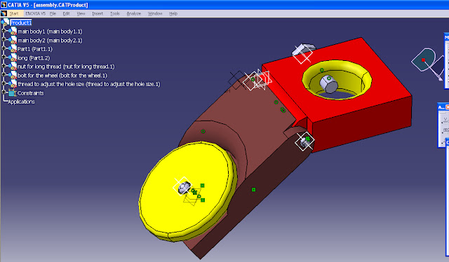
The last step after assembling all the components coloring was done on the final product.
+of+New+Bitmap+Image+(5).bmp)
Product Drafting


After that the second main body was drawn. I contains a pocket that will host the wheel with internal thread for the fastener to hold the wheel. There is also internal thread to fasten the two main bodies together. The two figures below show the second main body.


The the wheel was drawn as shown in the figure below.

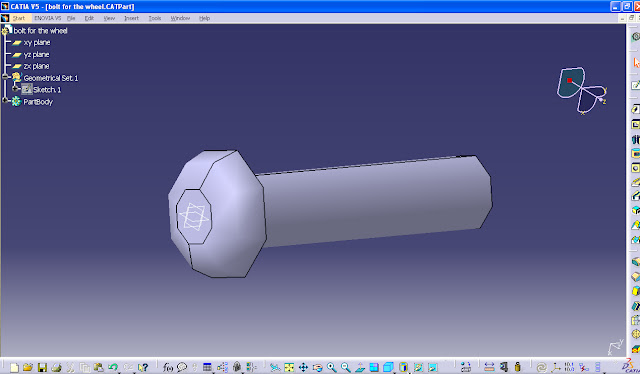
After that the fasteners were drawn and they are shown in the figure below.


When all the parts had been drawn the assembly task started.
+of+New+Bitmap+Image+(5).bmp)
After that the wheel was attached to the assembly.
+of+New+Bitmap+Image+(5).bmp)
The the fasteners are attached.
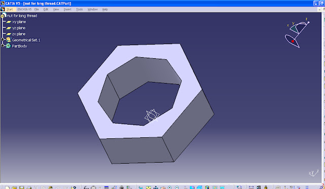
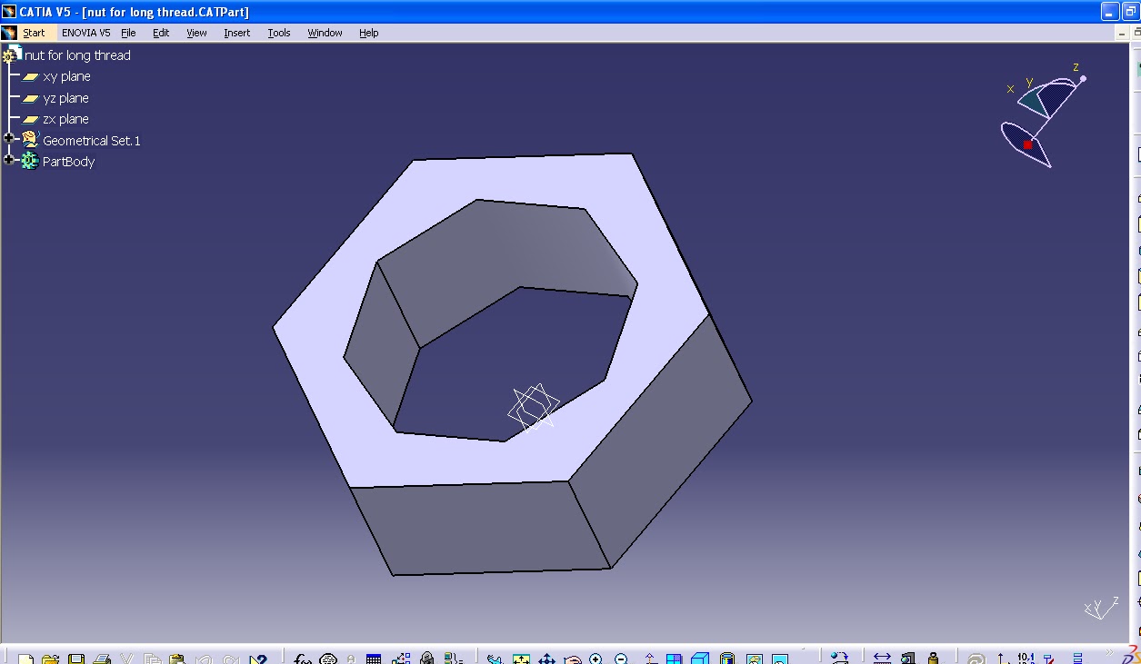
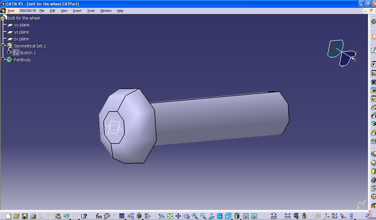
The figure below shows the long thread that is used to hold the two main bodies together.

The a nut inserted on the other end to fasten and fix the two main bodied together. This nut also used to loosen and tighten to allow more flexibility to the user to adjust the orientation base on the desired angle.

The wheel then is fixed on the main body using a thread and it is made with clearance to allow the wheel to rotate freely.
+of+New+Bitmap+Image+(5).bmp)
The last part to be fastened is the thread that is used to adjust the size of the hole. After inserting the pen/pencil or drawing, this fastener is used to hold the inserted part properly base on its dimension. This allow the user to use any size of pen, pencil, or marker in specific range to draw straight line using the line drawer.

+of+New+Bitmap+Image+(5).bmp)

Product Drafting
After doing the CATIA drawing, drafting was done in order to be sent to the production department to produce the required parts. Each component in the Line Drawer was drafted individually in addition to the draft of the full product which shows the assembly of the parts together and also the bill of materials. ISO standards were used in drafting with landscape views and first angle standard for projection method. The scale, the size of the paper, and other information can be found in the title box of each drawing.


Finally the assembly is shown in the draft below:

No comments:
Post a Comment